Back
 |
High Resolution Beam Imaging System
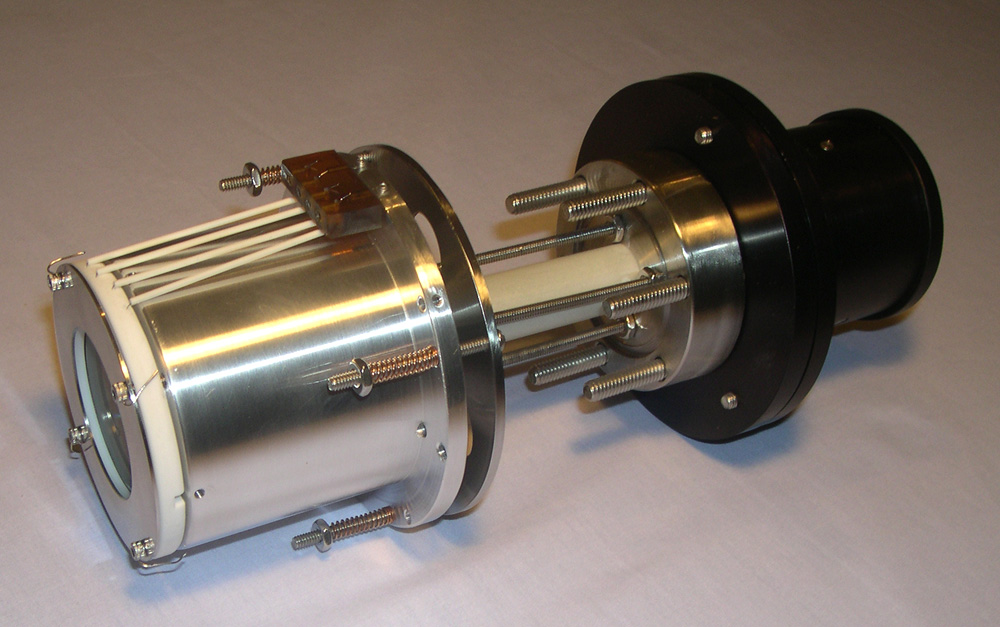
High Resolution Beam Imaging is made possible with the Beam Imaging Solutions HRBIS systems. The HRBIS can be used to measure two or three dimensional intensity distributions of ion, electron and neutral beams. The HRBIS can also be used to image X-rays for applications such as pinhole imaging and spectroscopy.
|
Technical Information
System Configuration
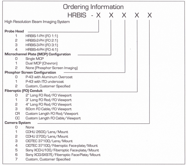
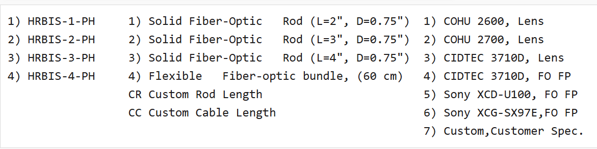
The probe heads, fiberoptic conduits and camera systems shown below are all interchangeable. The systems can be custom configured to meet your particular system requirements by specifying the appropriate HRBIS model number (see the table above).
Probe Heads Coherent Fiber-Optic Conduits Camera System
(with 2.75″ Conflat®, Fiber-Optic Viewport) (with camera mount systems)
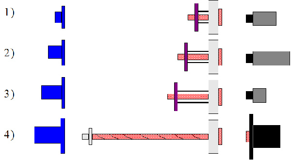
The HRBIS systems consist of three basic components:
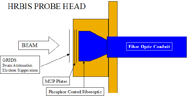
1) the HRBIS probe head which houses the MCP and phosphor screen;
2) a fiber-optic conduit which optically transmits the image from the probe head to a fiber-optic vacuum feedthrough; and,
3) a camera system for digital readout of the image. These components are described in detail below.
Probe Head
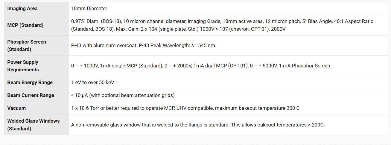
Probe Head Specifications
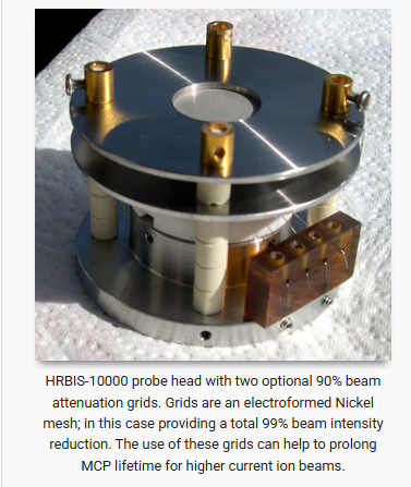
Probe Head – Optional Configurations
Probe heads are available with a single MCP (standard) or dual MCP (chevron) configuration for increased gain. MCP’s are imaging grade and are available with optional coatings on the MCP input face. Coatings include CsI, CuI, MgF2, MgO, KBr, Cu, and Au.
The phosphor screens come standard with P-43 phosphor and conductive aluminum over coating. Other phosphors are available upon special request, as well as an Indium-Tin-Oxide (ITO) under coating. ITO screens are generally used when lower electron accelerating voltages are required, however the quantum yield may be lower than that of aluminized screens.
The probe heads also have the capability of mounting a variety of apertures, slits, lenses, pinholes, filters and grids using 1/8″ (3mm) diameter ceramic mounting rods. Beam Imaging Solutions offers a small selection of grids that can be mounted in front of the probe head for applications such as electron suppression, beam attenuation, and beam acceleration. A 4-terminal high voltage feedthrough on 2 3/4″ (DN35) conflat® flange is provided with the HRBIS system for the phosphor screen and MCP voltage application.
Fiber-Optic Conduits
Images are transmitted optically from the probe head through one of two types of FO conduits to a 2 3/4″ (DN35) conflat® FO vacuum viewport. The image can then to be recorded on the outside of the vacuum chamber with a CCD/CID camera (see CCD and CID camera options below).
Conduits consist of either a flexible 60cm long, 10mm x 8mm rectangular FO cable (Remote Systems) or 19mm diameter solid FO rod (Standard Systems) which are available in various lengths. Both conduit types attach at one end to the HRBIS probe head, and to the FO viewport at the other end. The remote systems with flexible FO cable are especially useful for imaging particle beams deep within the vacuum chamber where the beam cannot be brought to a vacuum port for imaging.
The 60cm length is standard, however other lengths are available on request. The standard systems with solid FO rod are generally used when the beam can be brought close to a vacuum port for imaging.
The FO rod is available in various lengths to allow for greater flexibility when adapting to a customer’s particular application.
CCD and CID Camera Options
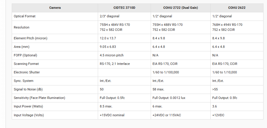
Optional CCD and CID camera readout systems are available for all HRBIS systems. All cameras are available with lens, video monitor and mounting system for imaging the FO viewport. The CIDTEC 3710D is also available with Fiber-Optic Face Plate (FOFP) directly attached to the camera sensor. The camera sensor is then mounted in a special housing which allows them to directly mate to the FO viewport. This direct FO coupling approach ensures highest possible resolution and gain. Cameras can be connected to a video monitor in order to observe images in real time, and can also be connected to a video frame grabber making it possible to store and analyze the images later. Beam Imaging Solutions offers optional Image Processing Systems (IPS) which include video monitor, frame grabber, cables and software. Beam Imaging Solutions is now offering the Sony XCD-U100 ( IEEE1394.b) and the Sony XCG-SX97E (GIGE) cameras with fiberoptic faceplates. Please contact Beam Imaging Solutions for more information.
CCD/CID Camera Specifications
Dimensions
HRBIS Standard Systems (Fiberoptic Rod Conduit)
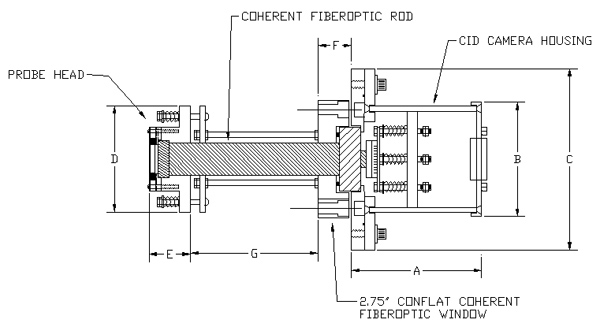
Dimensions (Shown with optional CIDTEC 3710D camera)
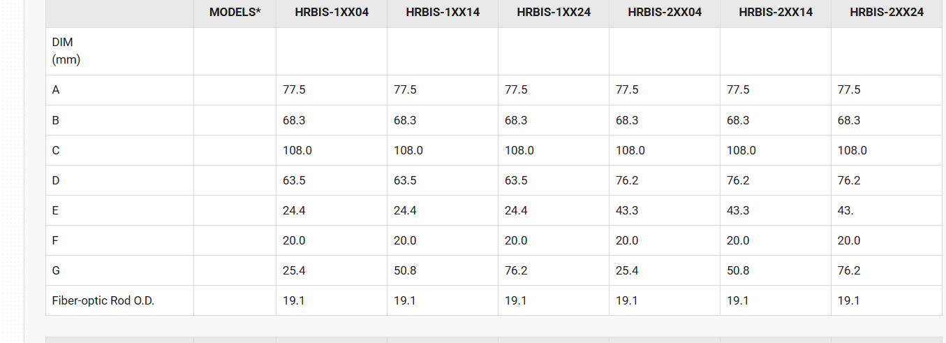
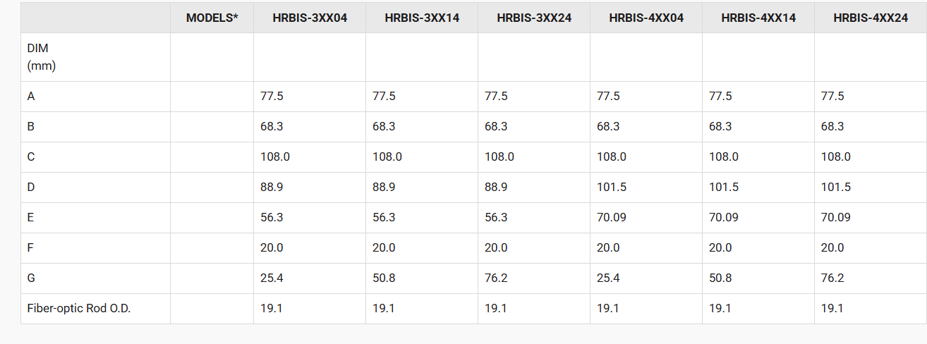
* The model number X descriptor determines the MCP and phosphor screen options (See ordering Information Table at top of Web Page).
HRBIS Remote Systems (Flexible Fiberoptic Cable)
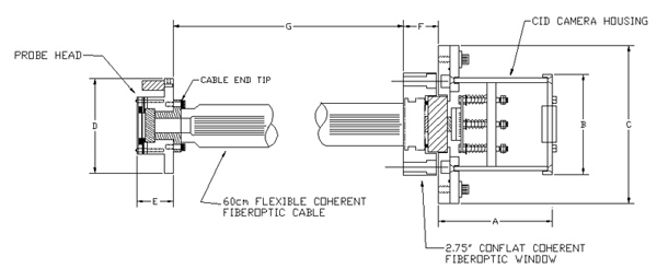
Dimensions
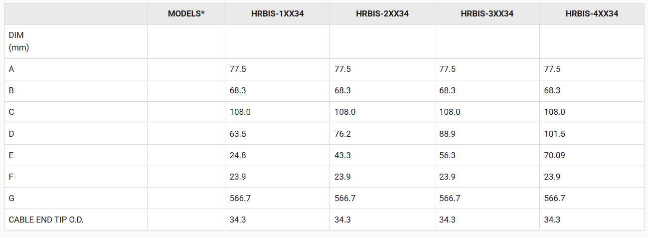
* The model number X descriptor determines the MCP and phosphor screen options (See ordering Information Table at top of Web Page).