Back
WEIGHT - 115 pounds (52.3 kg)
WIDTH - 15.125" (38.5 cm)
HEIGHT - 24.5" (62.3 cm)
LENGTH - 23" (58.4 cm) over handles
INPUT - 110-125 volts (220-250 volts optional) 50-400 hz A.C. or 12 volts D.C. (optional)
IMPULSE - 6 nanosecond rise time, 450 joules at 30kv continuous, up to 612 joulesat 35kv intermittent, random timing (6 second cycle at 30kv)
TESTING - 6 ma to 35kv, 1% ripple
CASE - Aluminum with grey finish
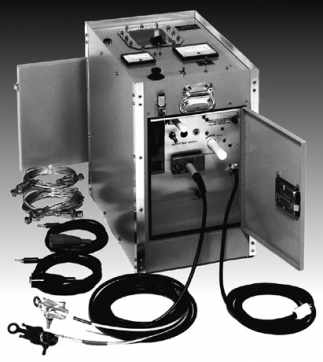
This two man portable unit contains:
A 35kv 1mfd. low inductance impulse service capacitor.
A VON continuously adjustable impulse control gap.
High reliability VON voltage doubler circuit with silicon rectifiers.
The fully protected output meter in the high voltage lead indicates true leakagereadings. Ranges 0-10 mic, 0-30 mic, 0-100 mic, 0-300 mic, 0-1 ma, 0-3 ma,0-10 ma.
Megohm scales on the output meter allow direct resistance reading from 100,000 ohms to 300,000 megohms.
A 0-5 amp A.C. ammeter in input of the 110 (220) volt to 13kv air insulated epoxyimpregnated high voltage transformer.
A rugged taut band high torque kilovoltmeter wit ranges of 0-10kv, 0-35kv.
A variable autotransformer for continuous voltage adjusment.
Power on and off-discharge switch discharges cable through a 2.5 megohm resistor.
Two ground relay systems require that the case ground, the 120 volt source ground, and the test lead ground be within 100 ohms or each other in order to operate the unit.
Separate sockets for testing and fault locating
Varistors are provided between the 120 volt input lines and the case to provide surge protection to the equipment.
Shielded test lead, 35 feet (10.6M) long. Other lengths are available such as 60 feet and 75 feet.
Optional built in inverter with 15 ft.(4.6m) battery leads permits operation from a 12 volt truck battery
THEORY: The capacitive discharge system is the most universally accepted way to locate underground cable faults. It is still the only system that works reliably on shielded cable such as URD type concentric neutral cable.
The basic capacitor discharge system consists of a capacitor, a high voltage D.C. power supply, and a means of connecting and disconnecting the capacitor to the center conductor of the faulted cable such as an impulse control gap. These components are shown in the simplified diagram below. The fault is shown as a gap. This is an accurate description of faults on URD type cable since a fault is a hole or cut in the insulation between the center conductor and the grounded semiconductor, shield wires and earth.
The objective of the system is to dump the stored electrical energy in the impulse capacitor into the cable fault such that an audible noise or thump is made. The thump should be loud enough to be heard and felt by personnel without detectors walking above the cable. The amount of energy available at the fault to "thump" the ground or ductwork is related to the characteristics of the fault gap, the electrical impedance of the path from the discharge capacitor to the fault and back, the energy in the discharge, the voltage of the discharge, and the rise time of the discharge. A fast rise time provides maximum noise at the fault with the least energy.
After each discharge, the power supply must charge the capacitor bank. The variable autotransformer on the power supply is used to adjust the rate of discharge. VON systems are designed for a continuous rate of discharge every six seconds at 30kv. The discharge voltage of the capacitor is related to the impulse control gap voltage and the fault gap voltage since they are in series. By adjusting the impulse control gap, the impulse capacitor can be charged to its rated voltage regardless of the characteristics of the fault gap. This allows the fault to be located with minimum energy and voltage. To locate a fault the voltage rating of the discharge capacitor must exceed the voltage rating of the fault gap. The 35kv maximum discharge voltage has proven to be sufficient for all presently installed solid dielectric distribution cable.
Instruction Manuals
Instruction manuals are linked here. Please note that there are differences between the original "BI-.35" and the newer "BI-.35S" or "BI-.35S1", so please make sure you download the correct manual for your unit. If your nameplate is missing, the easiest way to tell the difference is the handle of the high voltage lead. If the handle is aluminum, you have a BI-.35. If the handle is all fiberglass, you have a BI-.35S or BI-.35S1.